Welcome to the analog-tutorials wiki!
This wiki covers getting started with open-source analog IC design tools. The basic flow is xschem for schematic capture, simulation, and SPICE netlist generation, then KLayout for layout.
Start by setting up the IIC-OSIC-TOOLS container, following the Setting Up Open Source Tools with Docker tutorial.
Pages
Once your environment is set up, work through the following examples, taking each block from schematic to layout:
Literature recommendations
- Practical Electronics for Inventors by Paul Scherz
- Fundamentals of Microelectronics by Behzad Razavi
- CMOS VLSI Design, A Circuits and Systems Perspective by Neil H. E. Weste and David Money Harris
- Open Circuits: The Inner Beauty of Electronic Components by Windell Oskay
- AIC2023 and other years (e.g. AIC2026) teaches core analog IC concepts while building circuits on the SKY130 PDK
- Electric Circuits, 12Ed, 2023, Nilsson, Riedel
- Microelectronic Circuits, 8Ed, 2019, Sedra, Smith, Carusone
- Fundamentals of Microelectronics, 3Ed, 2021, Razavi
- Modern Semiconductor Devices for Integrated Circuits, 2009, Hu
- Analog Integrated Circuit Design, 2Ed, 2011, Johns, Martin, Carusone
Learning resources
- Xschem editor commands
- Basic operations on KLayout
- Terminology overview
- Test Verilog and Digital Logic with EDA Playground
- Tutorial and overview on ngspice control language
- Learn Linux with Bandit
Associated
Inverter: Schematic to Layout
This page walks through building a basic CMOS inverter in xschem, simulating it, and then laying it out in KLayout. By the end you'll have a working schematic, a passing DC/transient sim, and a DRC-clean layout ready for LVS.
Overview
The inverter is the simplest CMOS logic gate and a good first exercise for the full analog flow: schematic capture in xschem, SPICE simulation with ngspice, and layout in KLayout. Working through it end-to-end will introduce you to PDK device symbols, sizing conventions (W/L ratios), and the basic layout rules you'll reuse in every later block.
Prerequisites
- IIC-OSIC-TOOLS container set up and running
- In this tutorial we'll be using the SKY130PDK
Schematic
Open the terminal (it should auto be in the directory /foss/designs) and run:
sak-pdk SKY130A
xschem
- Click the
+symbol to open up a new schematic. You should now have a blank slate titleduntitled.sch - Right click -->
Insert symbol--> place an NMOS and PMOS device from the PDK symbol library, thenFile -> Save as -> inverter.sch - Wire the gates together as the input, and the drains together as the output. Tie the PMOS source to VDD and the NMOS source to VSS
Ctrl + PorSymbol --> Place schematic input portCtrl + Shift + PorSymbol --> Place schematic output port- Double click on a pin or press
qto open its properties, and replace XXX with the pin name
- Set device sizing (W/L) for the desired switching threshold. Here, we make PMOS 3x wider (so w=3) while NMOS w=1
- Press
aorSymbol -> Make symbol from schematicto create a symbol from the schematic
Simulation
Open a new schematic (inverter_tb.sch), place your inverter symbol, and add a 1.8 V supply, a pulse source on the input, and a small load cap on the output. Netlisting it from xschem gives you something equivalent to the testbench below:
* inverter_tb.spice : DC sweep + transient, sky130 tt
.lib $PDK_ROOT/sky130A/libs.tech/ngspice/sky130.lib.spice tt

.subckt inverter IN OUT VDD VSS
XM1 OUT IN VSS VSS sky130_fd_pr__nfet_01v8 W=1 L=0.15
XM2 OUT IN VDD VDD sky130_fd_pr__pfet_01v8 W=3 L=0.15
.ends

Xinv in out vdd 0 inverter
Vdd vdd 0 1.8
Vin in 0 pulse(0 1.8 1n 50p 50p 2n 4n)
Cload out 0 10f

.control
dc Vin 0 1.8 0.01
meas dc vm find v(in) when v(out)=0.9
tran 10p 10n
meas tran trise trig v(out) val=0.18 rise=1 targ v(out) val=1.62 rise=1
meas tran tfall trig v(out) val=1.62 fall=1 targ v(out) val=0.18 fall=1
.endc
.end
Run it:
ngspice inverter_tb.spice
vmis the switching threshold: where the DC transfer curve crosses VDD/2. With PMOS 3x wider it should sit close to mid-railtrise/tfallare the 10-90% output transition times into the 10 fF load
Layout
pip show gdsfactory kfactory
pip install "gdsfactory<8"
Add --break-system-packages if pip refuses.
Draw the cell
Open KLayout in edit mode (plain klayout opens as a viewer without editing perms):
klayout -e
File -> New Layout, select thesky130Atechnology, name the top cellinverter- Place the transistors: press
i(Instance), pick the SKY130 PCell library, and place onenfet_01v8and onepfet_01v8. Double click each to set W/L matching the schematic (NMOS 1u/0.15u, PMOS 3u/0.15u) - Stack the PMOS above the NMOS with the gates aligned in a single vertical column. The PMOS PCell generates its own nwell; if you resize the device, make sure the well still encloses it
- Add well taps: an n-tap inside the nwell tied to VDD, and a p-tap tied to VSS. The layout will look done without them, but it will fail LVS and the real circuit would be latch-up prone
- Route the cell:
- Gates: join the two poly gates, then drop a poly contact (licon needs npc over it) for the input
- Drains: strap the NMOS and PMOS drains together on li1 for the output
- Rails: met1 VDD rail across the top, VSS across the bottom, with mcon vias down to the sources and taps
- Label the pins: place text labels
IN,OUT,VDD,VSSon the pin purpose of the layer they land on. LVS matches ports by name, so these must match the schematic pins exactly - Export GDS:
File -> Save As -> inverter.gds
DRC
klayout -b -r $PDK_ROOT/sky130A/libs.tech/klayout/drc/sky130A_mr.drc \
  -rd input=inverter.gds -rd report=inverter_drc.lyrdb
Load the report in KLayout via Tools -> Marker Browser and fix violations until clean.
LVS
Extract a SPICE netlist from the layout with Magic:
magic -dnull -noconsole -rcfile $PDK_ROOT/sky130A/libs.tech/magic/sky130A.magicrc
Then in the Magic console:
gds read inverter.gds
load inverter
extract all
ext2spice lvs
ext2spice
Export the schematic netlist from xschem (Netlist button, make sure the top level is a .subckt) and save it as inverter_sch.spice. Then compare the two with netgen:
netgen -batch lvs "inverter.spice inverter" "inverter_sch.spice inverter" \
  $PDK_ROOT/sky130A/libs.tech/netgen/sky130A_setup.tcl
You want the final report to say the circuits match uniquely.
Concluding
Once this works, try the Ring Oscillator, which chains five of these inverters into a loop.
Questions? Ask in the network Discord.
Ring Oscillator
A 5-stage ring oscillator on SKY130, from schematic to simulated frequency. This page doubles as the formatting reference: every construct the renderer understands is used somewhere below.
TL;DR: an odd number of inverters in a loop has no stable DC operating point, so it oscillates at roughly
f = 1 / (2 * N * t_pd). Five stages of the standard inverter lands near 1.2 GHz at tt.
Overview
The ring oscillator is the hello world of analog design: it needs correct device models, a working simulator, and nothing else. If this page simulates cleanly, your toolchain setup is good and every later tutorial will run.
Inline styles for reference: bold, italic, both, inline code, struck, and an external link to the SKY130 PDK docs.
Prerequisites
xschemandngspiceinstalled and on$PATH- SKY130A PDK with
$PDK_ROOTexported- built with
open_pdks - includes the
sky130_fd_prprimitives library
- built with
- Basic familiarity with SPICE netlists
Schematic
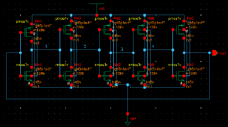
Keep the loop symmetric: identical W/L on every stage, and buffer the tap so the probe capacitance does not load the ring.
Netlist
* ring_osc.spice : 5-stage ring oscillator, sky130 tt
.lib $PDK_ROOT/sky130A/libs.tech/ngspice/sky130.lib.spice tt

.subckt inv in out vdd gnd
XM1 out in gnd gnd sky130_fd_pr__nfet_01v8 W=1   L=0.15
XM2 out in vdd vdd sky130_fd_pr__pfet_01v8 W=2.1 L=0.15
.ends

Xi1 n5 n1 vdd 0 inv
Xi2 n1 n2 vdd 0 inv
Xi3 n2 n3 vdd 0 inv
Xi4 n3 n4 vdd 0 inv
Xi5 n4 n5 vdd 0 inv

Vdd vdd 0 1.8
.ic v(n1)=0
.tran 10p 20n
.end
Run it
- Export the environment
export PDK_ROOT=/usr/local/share/pdk
- Launch the simulation
ngspice ring_osc.spice- wait for the transient to finish
- Measure the period on
v(n5)and invert it
Results
| Corner | VDD | f_osc | Power |
|---|---|---|---|
| tt | 1.80 V | 1.21 GHz | 84 uW |
| ss | 1.62 V | 0.89 GHz | 61 uW |
| ff | 1.98 V | 1.63 GHz | 118 uW |
Frequency tracks 1/t_pd, so expect roughly linear movement with VDD across corners.
Checklist
- schematic drawn, ERC clean
- transient runs at tt
- ss / ff corners swept
- layout drawn, DRC and LVS clean